Bode example diagrams rules constructing lpsa swarthmore edu
Table of Contents
Table of Contents
As electrical engineers, we frequently come across transfer functions that describe the behavior of a system. A Bode plot is a graph that represents the frequency response of a system. Drawing a Bode plot from a transfer function can be a daunting task, but it is crucial in analyzing the behavior of a system. In this article, we will explain how to draw a Bode plot from a transfer function, step-by-step.
When it comes to drawing a Bode plot from a transfer function, some of the pain points that engineers often experience include confusion with Bode plot basics, difficulties in factorizing transfer functions, and choosing appropriate breaks between decades. Understanding these pain points is essential to successfully graph the data.
Drawing a Bode plot requires a systematic approach. The steps necessary to draw the plot include understanding the Bode plot basics, identifying or factorizing the transfer function, determining the break frequencies, and finally drawing the plot.
Now that we have identified pain points related to drawing a Bode plot from a transfer function and mentioned the steps, let’s dive deeper into how to execute each step.
Bode plot basics
Before diving deeper into the process of drawing a Bode plot from a transfer function, it is crucial to understand the basics of a Bode plot. Any Bode plot consists of two parts: magnitude and phase. The y-axis usually represents the magnitude of the transfer function, while the x-axis represents the frequency of operation using a logarithmic scale.
The logarithmic scale is essential since it reduces the amount of data required to represent very high- and low-frequency behavior. Decades are popular choices on the x-axis, which means that the frequency increases by a factor of 10 between adjacent ticks of the axis. The behavior between these markers is then approximated by straight lines, making the plot more manageable.
Identifying or Factorizing the transfer function
The transfer function is the key to drawing the Bode plot. The transfer function is a mathematical function that relates the input signal to the output signal of a system. The transfer function could be either expressed as a ratio of two polynomials or generated numerically from a system model.
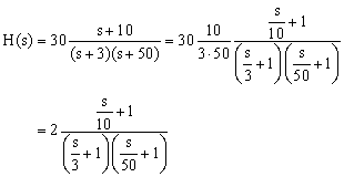
If the transfer function is given in its ratio form, it is important to factorize it into its poles and zeros. Poles indicate the roots of the denominator, whereas zeros indicate the roots of the numerator. Factoring the transfer function helps identify the functional form of the magnitude and the phase of the transfer function concerning frequency.
Determining the break frequencies
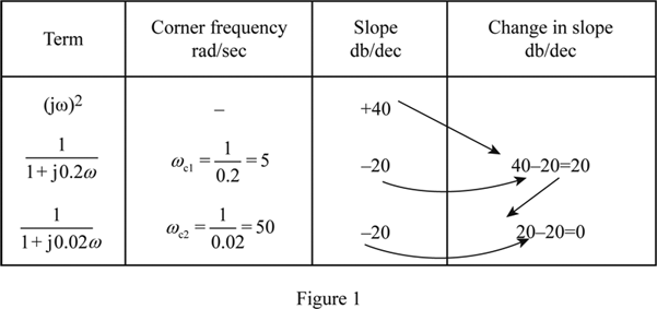
The break frequencies correspond to the points at which the behavior of the magnitude or phase begins to change. These frequencies are determined by setting the magnitude or phase expressions to -3 dB, which is corresponding to a factor of 1/√2. At high frequencies, the behavior of the magnitude is dominated by the poles, whereas at low frequencies, the behavior is influenced by the zeros.
Drawing the plot
The final step in drawing a Bode plot is the actual plotting of the data. By now, a clear picture of the two functions, magnitude and phase, should be known as a function of frequency. A draw the frequency axis in logarithmic form, choose appropriate break frequencies, and sketch each straight line section.
Now that we have described how to draw a Bode plot from a transfer function, let’s consider a personal experience where applying these steps helped to represent the data better.
Bode Plot Example
During my time in college, I took a class on the Principles of Communications Engineering. One major assignment was to draw a Bode plot from a given transfer function. Initially, I faced some difficulties since I was new to the concept, but taking time to understand the Bode plots basics helped me a lot in executing the process of drawing the Bode plot. Upon completion of the assignment, I was amazed by how easy it was to understand complex relationships represented in a graph.
Guidelines for Successfully Drawing Bode Plots
In order to successfully draw a Bode plot from a transfer function, we recommend following these steps:
- Understand the Bode plot basics
- Identify or factorize the transfer function
- Determine break frequencies
- Sketch the two functions in log-log form
Question and Answer
Q1. What is a Bode plot, and why is it important?
A Bode plot is a graph that represents the frequency response of a system. It consists of two parts: magnitude and phase. The y-axis usually represents the magnitude of the transfer function, while the x-axis represents the frequency of operation using a logarithmic scale. It is important because it illustrates how a system will respond to different frequencies of an input signal.
Q2. What is the logarithmic scale used in a Bode plot?
The logarithmic scale is used on the x-axis of a Bode plot because it reduces the amount of data required to represent very high- and low-frequency behavior, making the plot more manageable.
Q3. What are the break frequencies in a Bode plot?
The break frequencies correspond to the points at which the behavior of the magnitude or phase begins to change. These frequencies are determined by setting the magnitude or phase expressions to -3 dB, which is corresponding to a factor of 1/√2.
Q4. What are the steps required to draw a Bode plot from a transfer function?
The steps required are:
- Understand the Bode plot basics
- Identify or factorize the transfer function
- Determine break frequencies
- Sketch the two functions in log-log form
Conclusion of how to draw a bode plot from a transfer function
Understanding how to draw a Bode plot from a transfer function is a necessary skill for any electrical engineer. By following the four steps of understanding the Bode plot basics, factorizing the transfer function, determining the break frequencies and sketching the two functions in logarithmic form, the process of drawing a Bode plot can be executed successfully.
Gallery
Bode Plot Examples With Solutions | How Do You Make A Bode Plot

Photo Credit by: bing.com / bode magnitude plots nyquist
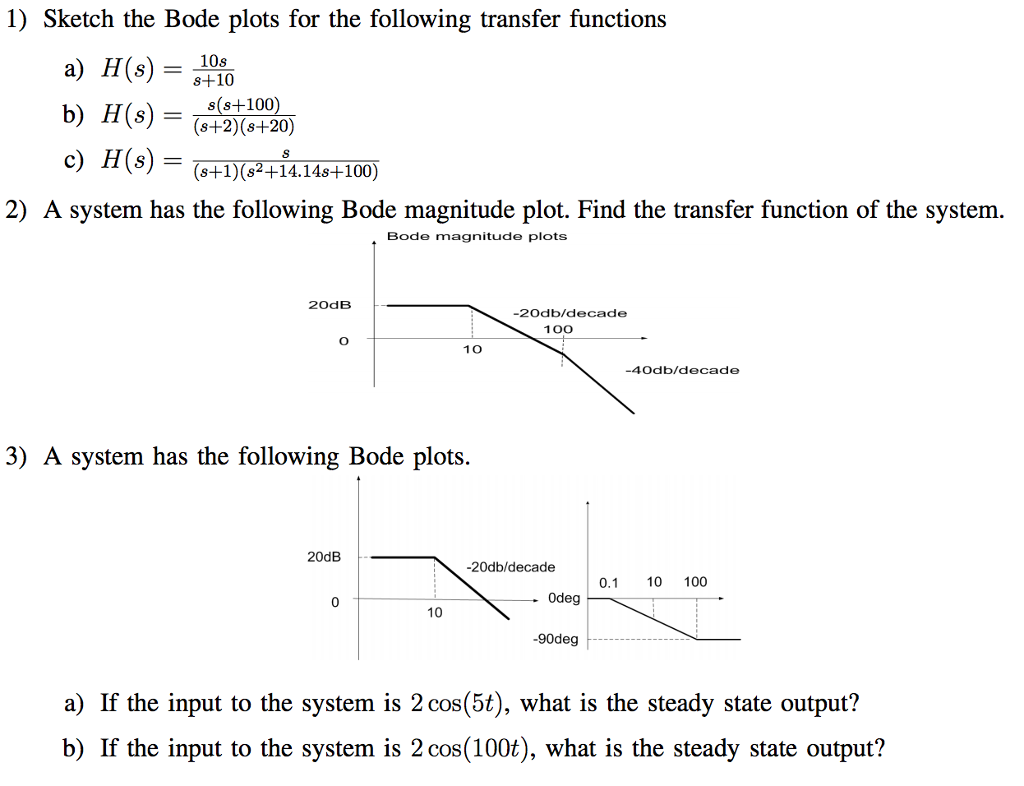
Solved Sketch The Bode Plots For The Following Transfer | Chegg.com

Photo Credit by: bing.com / bode transfer plots sketch following functions 10s plot function magnitude system solved s2 transcribed text problem been
Bode Plot EXAMPLE - YouTube

Photo Credit by: bing.com / bode plot example
Rules For Constructing Bode Diagrams - Erik Cheever

Photo Credit by: bing.com / bode example diagrams rules constructing lpsa swarthmore edu
How To Derive A Transfer Function Given A Bode Plot (Part 3) - YouTube

Photo Credit by: bing.com / bode


